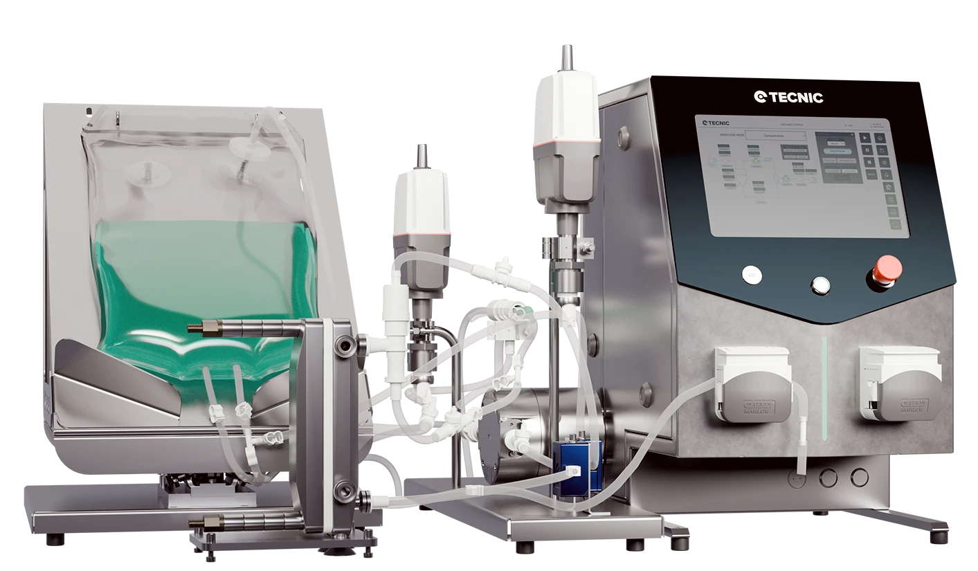
Hygienic vessel design in biopharma is not only about holding liquid safely. It is about giving the process a stable, controllable and clean environment where mixing, gas handling, temperature control and sampling can happen without creating unnecessary operational risk.
In laboratory bioprocessing, the vessel format shapes more than the setup. It influences temperature strategy, working volume, sterility approach, sensor layout, agitation behaviour and how easily a method can be transferred from one scale to the next.
That is why choosing between a glass reactor, a non-jacketed reactor or a single-use vessel should start with the process itself, not only with the material or the price point.
What makes a vessel hygienic in biopharma?
A hygienic vessel is designed so the process can be run, sampled, cleaned or replaced with minimum risk of uncontrolled contamination, dead zones or avoidable operational complexity. In biopharma, that means more than a clean-looking reactor body. It means the full interaction between vessel material, ports, seals, agitation, sampling points and thermal support has to make sense for the application.
At laboratory scale, the most useful vessel is often the one that keeps process behaviour clear and reproducible. That is why geometry consistency, access to probes and additions, and a practical temperature control strategy usually matter more than adding features that the process does not really need.
A hygienic vessel is not defined by one material alone. It is defined by how the whole vessel supports control, access, sterility and repeatable operation.
Glass, non-jacketed and single-use vessels, what changes?
These three formats can all be valid in bioprocess development, but they do not solve the same workflow in the same way. The best choice depends on how much temperature control is needed, how often the process changes and whether the product-contact path should be reusable or disposable.
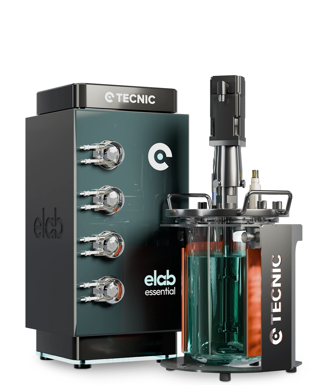
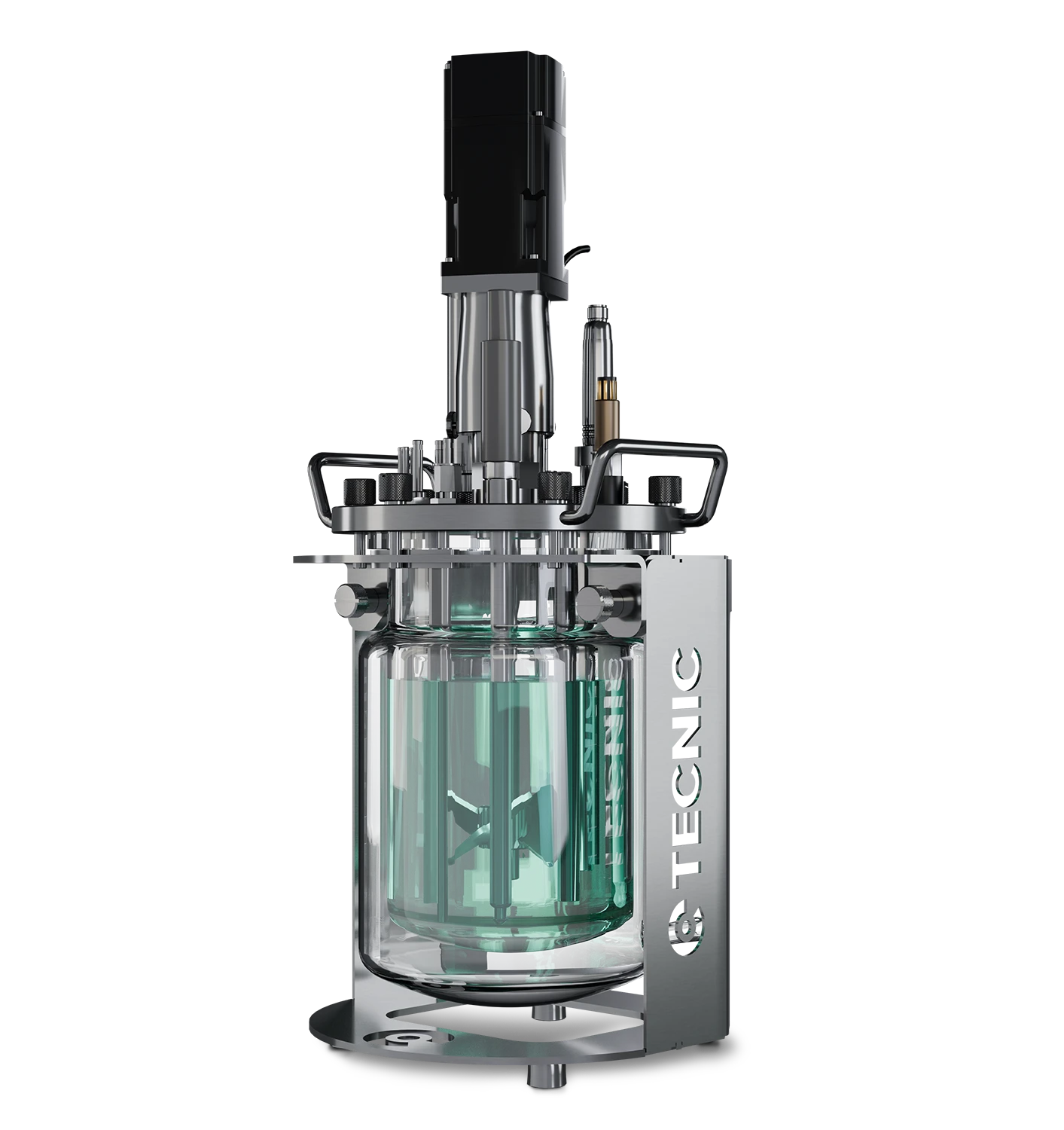
Glass reactor
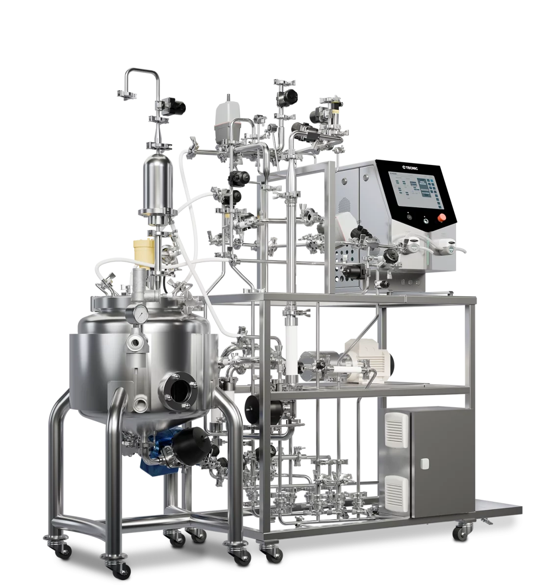
A jacketed glass reactor is usually the strongest option when the process needs controlled heating or cooling around the vessel body. TECNIC’s current glass vessel line covers 1, 2, 5 and 10 L and the catalogue presents both jacketed and non-jacketed formats with consistent geometry across sizes, which is useful for development and scale-up studies. :contentReference[oaicite:3]{index=3} :contentReference[oaicite:4]{index=4}
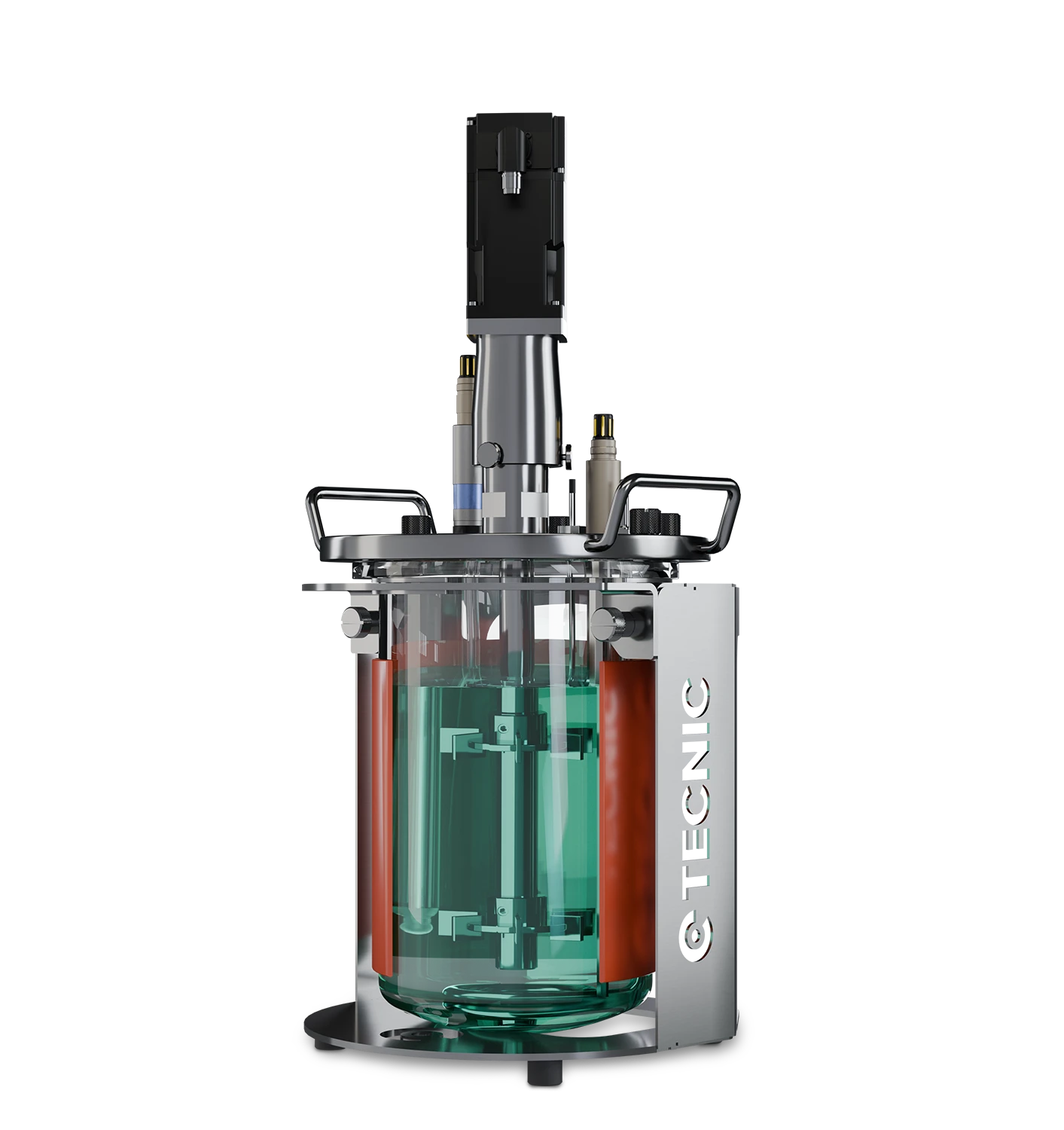
Non-jacketed reactor
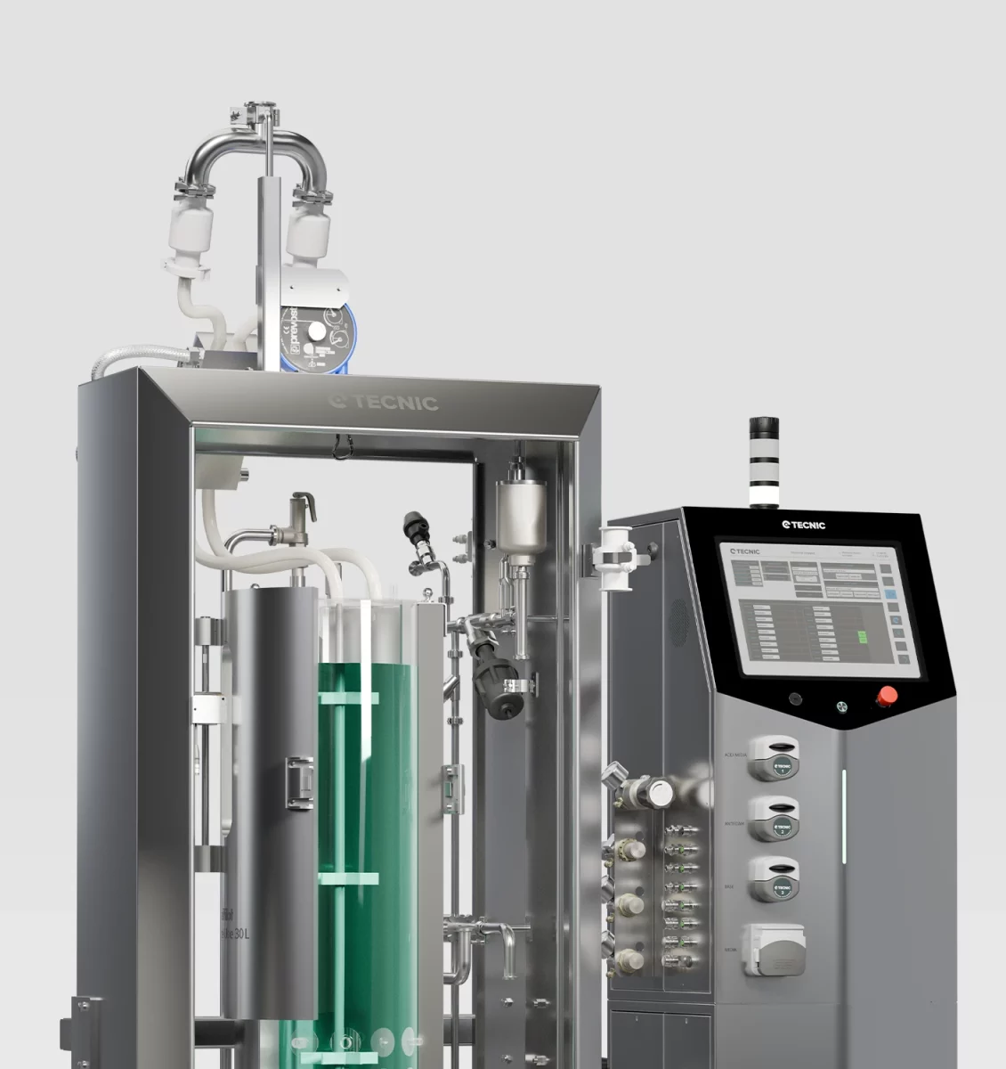
A non-jacketed reactor keeps the setup simpler and can be attractive when the laboratory already works with external temperature support or when the process does not need the same thermal control intensity as a jacketed vessel. TECNIC’s current page presents this format in 1, 2, 5 and 10 L with a heating blanket and cooling finger concept. :contentReference[oaicite:5]{index=5}
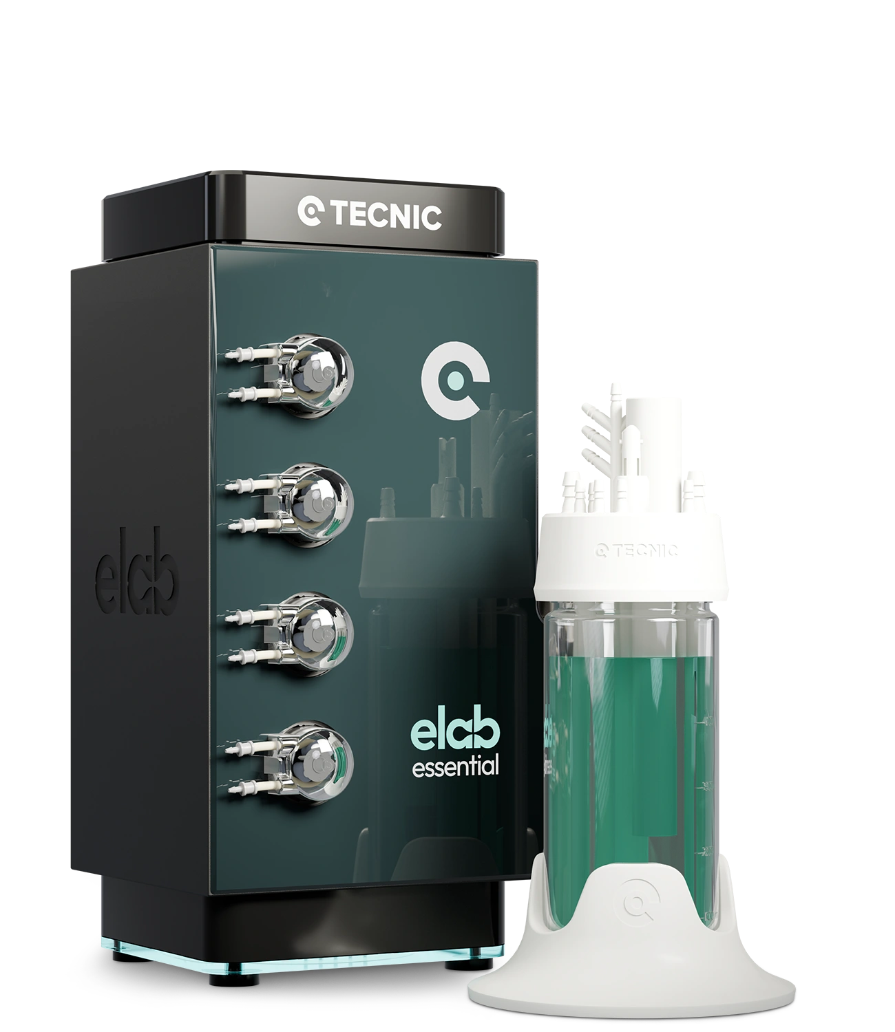
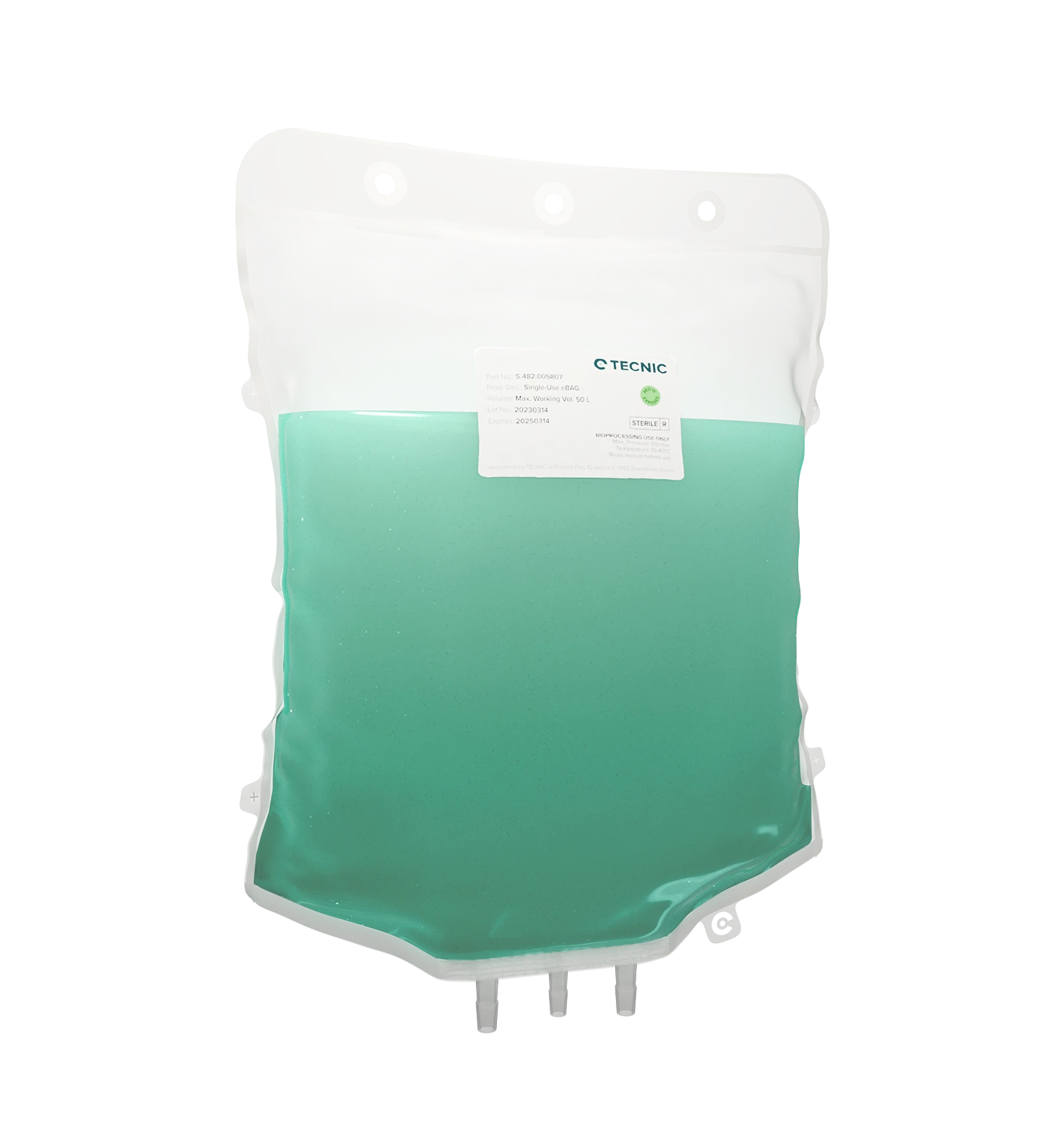
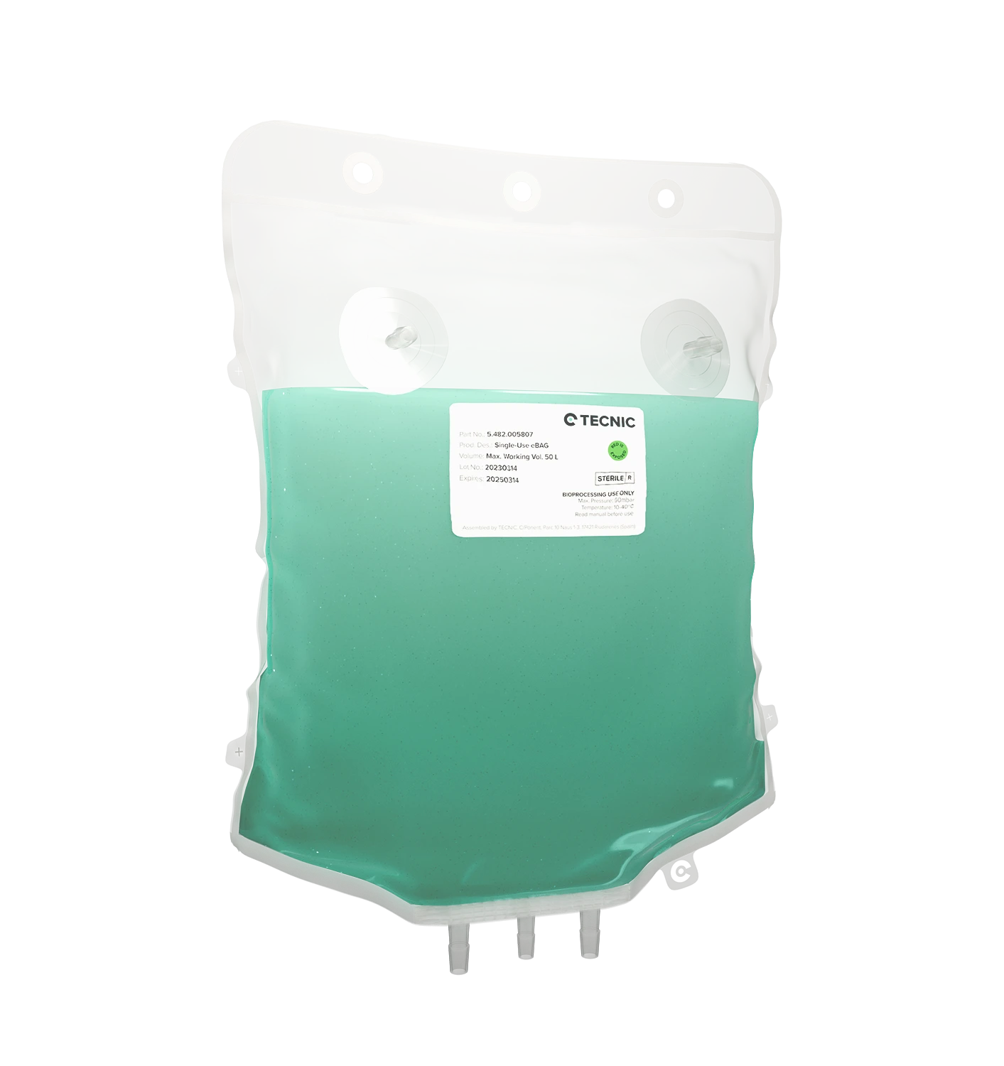
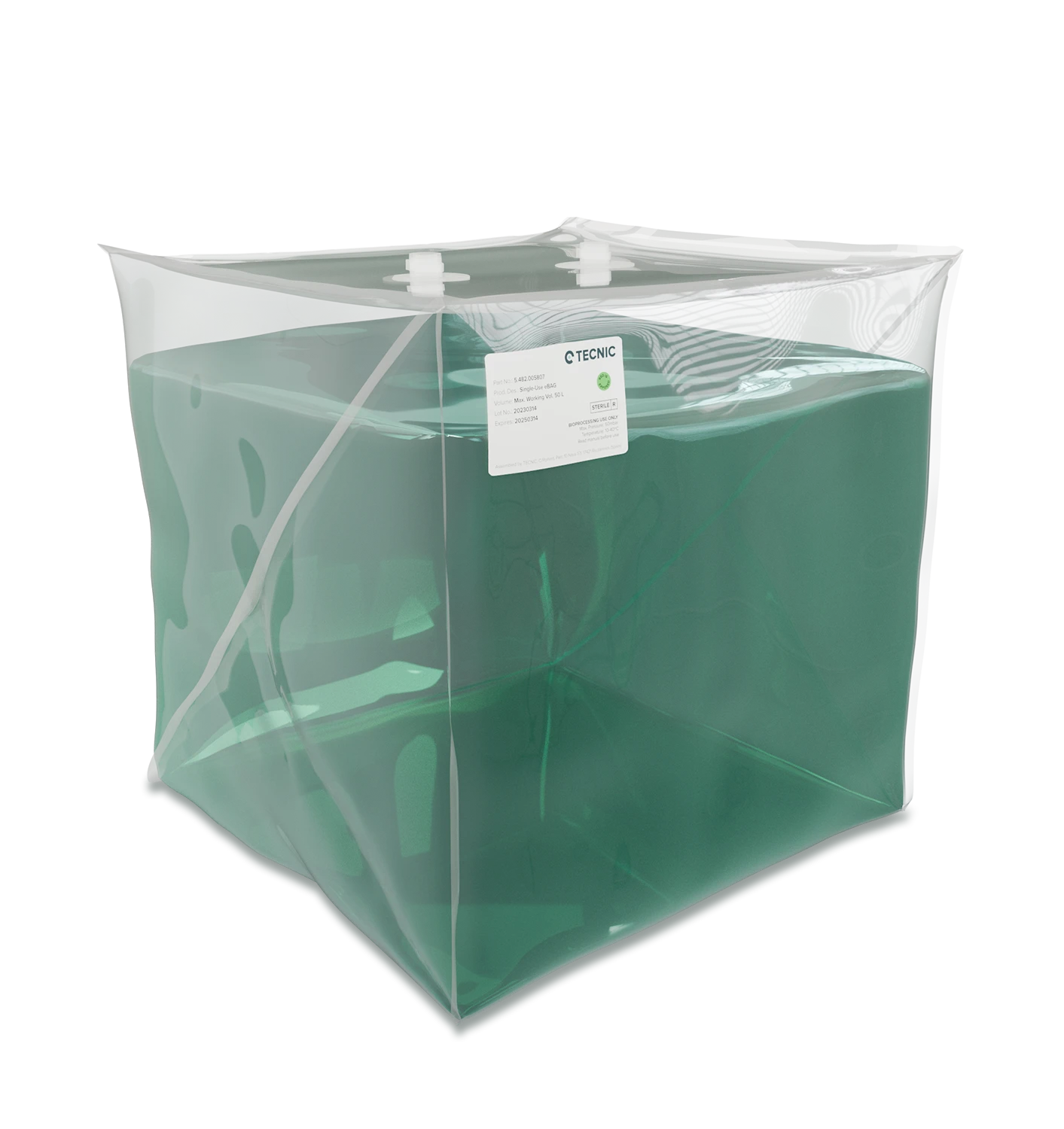
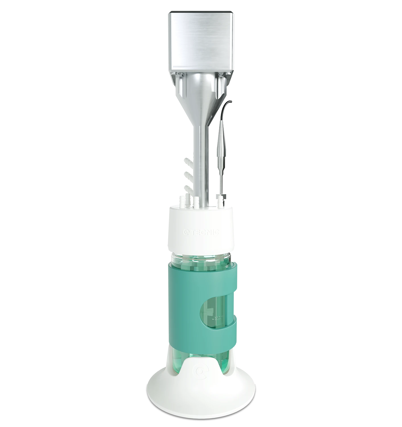
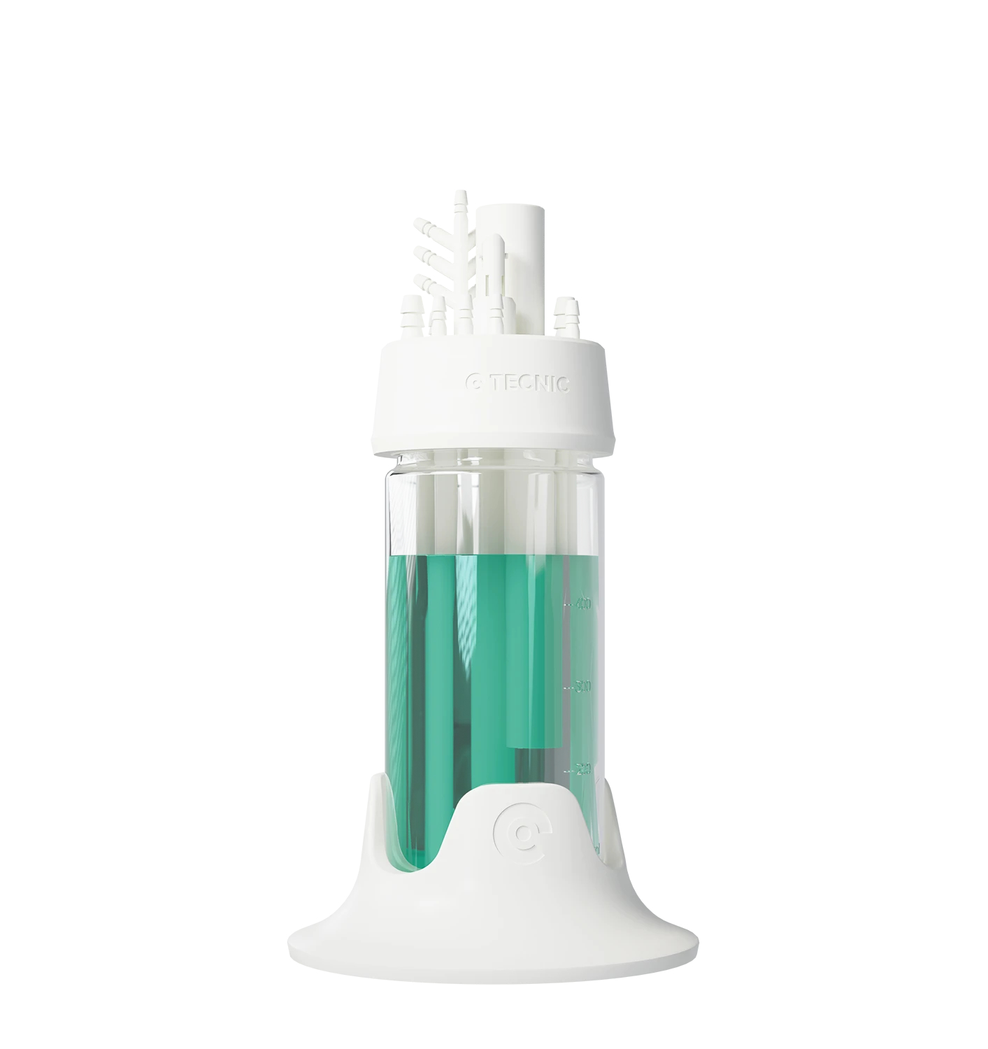
Single-use vessel
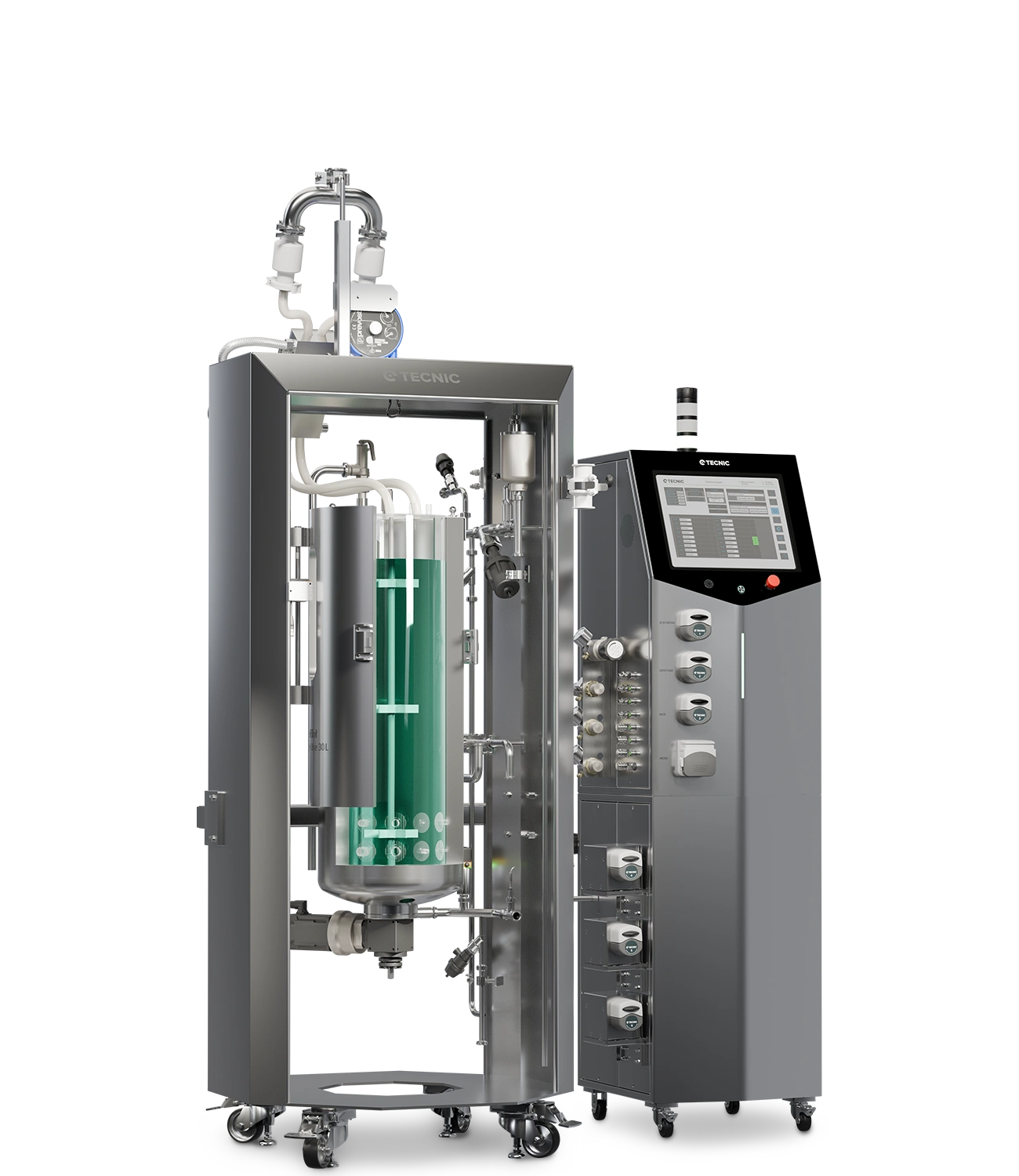
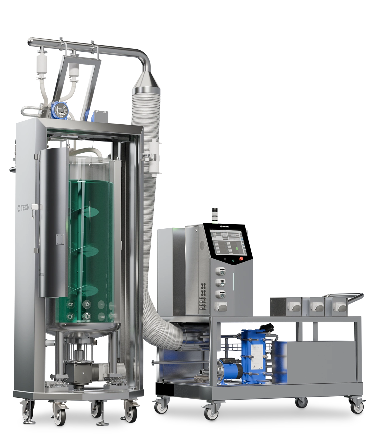
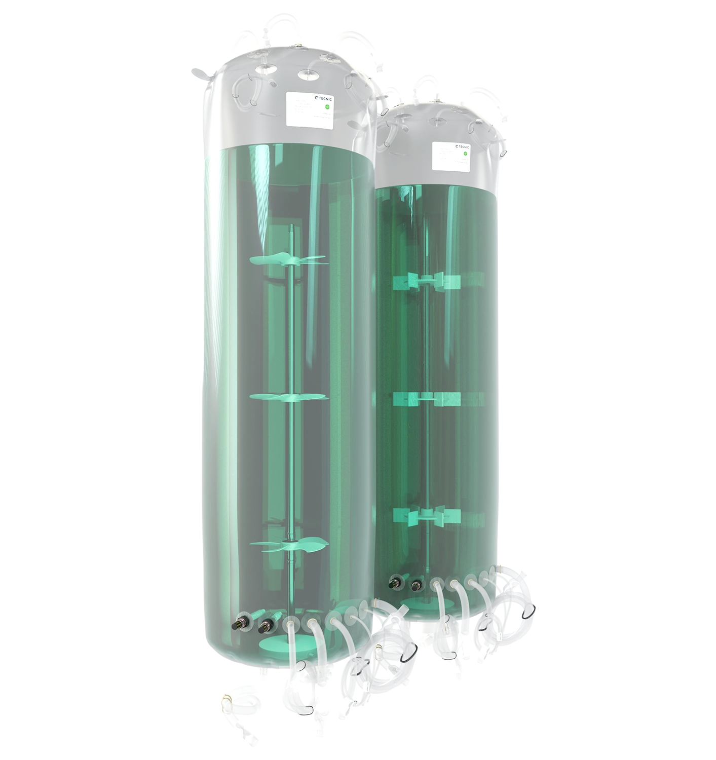
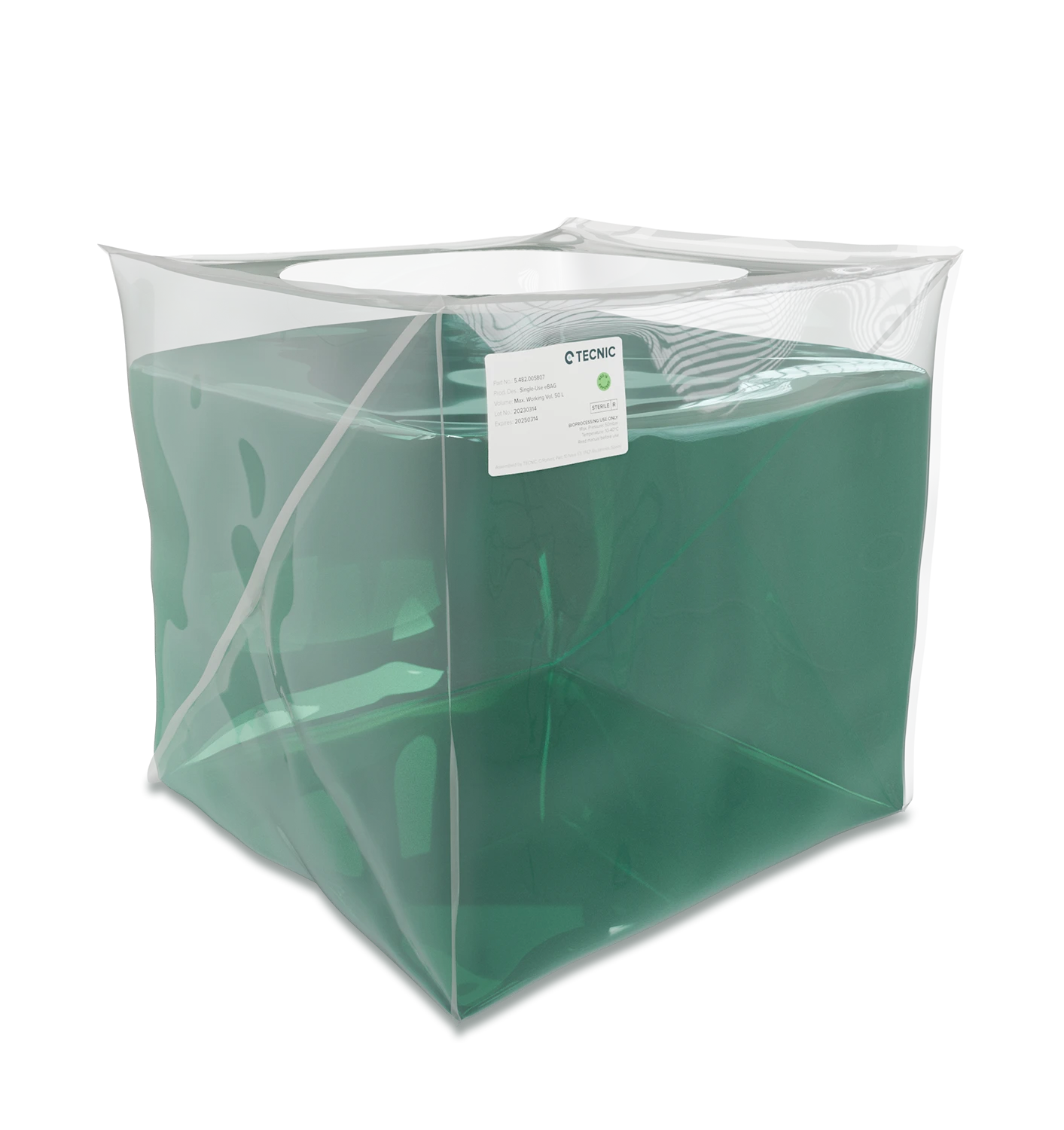
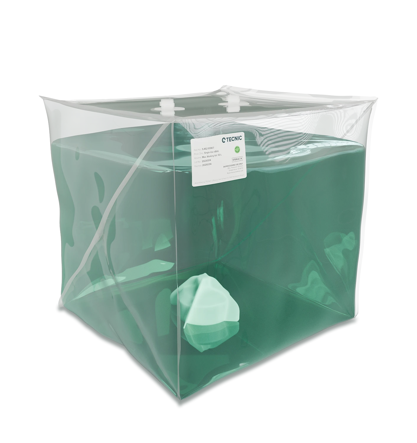
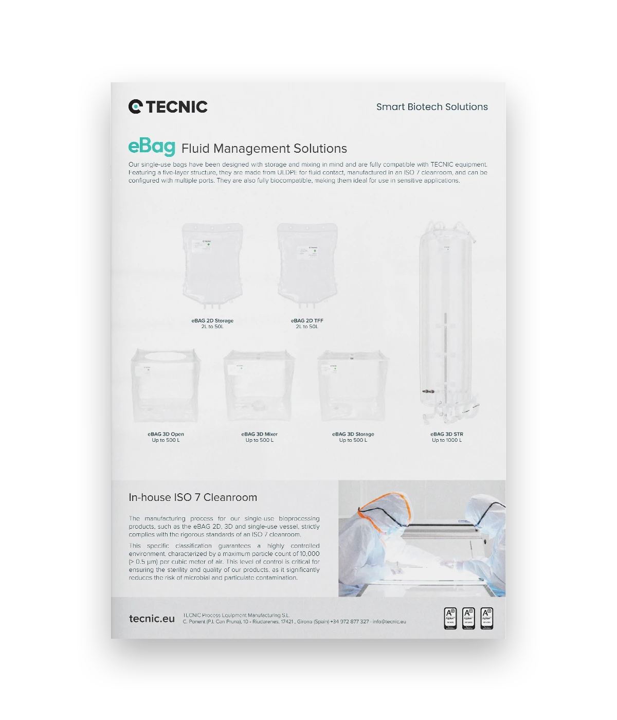
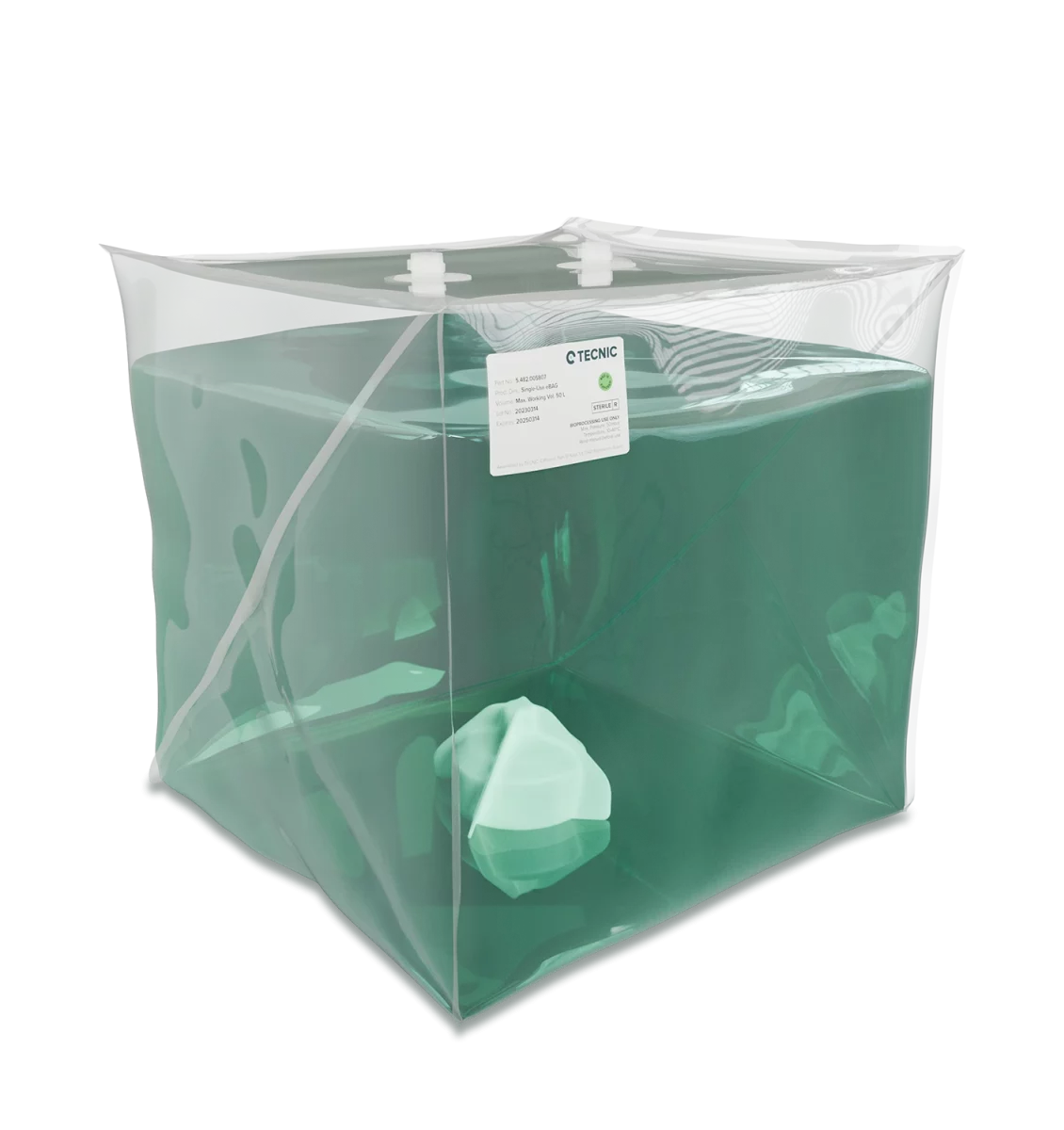
A single-use vessel changes the workflow more radically because the product-contact path becomes disposable. On TECNIC’s current vessel page, this format is positioned for 0.5, 1, 2 and 5 L, with gamma-sterilised consumables, microbial and cellular agitation configurations, and manufacturing under ISO 7 conditions. :contentReference[oaicite:6]{index=6}
Critical design points before selecting a vessel
A vessel should not be selected only by total volume. In practice, the useful decision comes from a smaller set of design criteria that directly affect process behaviour.
| Design point | Why it matters | Typical risk if ignored |
|---|---|---|
| Working volume range | Defines how stable agitation and probe coverage remain through the run. | Poor reproducibility at low or high fill levels. |
| Thermal strategy | Jacketed, non-jacketed or disposable paths behave differently. | Slow response or unnecessary system complexity. |
| Port layout | Impacts sensors, additions, gas lines, sampling and harvest. | Awkward routing or limited process flexibility. |
| Agitation concept | Shapes mixing, gas dispersion and shear behaviour. | Weak homogenisation or excessive stress on the culture. |
| Material and finish | Affects durability, compatibility and cleaning logic. | Lower hygienic confidence or harder maintenance. |
| Upgrade compatibility | Important when labs need to expand without changing the full setup. | Higher replacement cost and reduced flexibility. |
The best vessel is not the one with the longest specification sheet. It is the one that keeps the process understandable, controllable and practical for the team using it.
How to choose the right vessel for the process
A simple way to decide is to start with the process objective and the operating routine.
- Choose a glass reactor when you need precise thermal support and a robust reusable lab vessel path.
- Choose a non-jacketed reactor when simplicity and external temperature support are enough for the application.
- Choose a single-use vessel when reducing product-contact cleaning and simplifying changeover has clear value.
- Check the agitation logic if the process is microbial or cell culture, because the impeller concept should match the biological system.
- Check future compatibility if the lab may need to expand volumes, replace worn vessels or adapt the setup to new processes.
Comparison table
The most useful way to compare vessel types is by workflow and process behaviour, not only by material.
| Criterion | Glass reactor | Non-jacketed reactor | Single-use vessel |
|---|---|---|---|
| Typical scale | Laboratory development and scale-up studies. | Laboratory development with simpler thermal logic. | Laboratory development and disposable product-contact workflows. |
| Temperature strategy | Integrated jacket support. | External temperature support or simpler control logic. | Depends on the platform and support equipment around the consumable. |
| Cleaning logic | Reusable vessel path. | Reusable vessel path. | Disposable product-contact path. |
| Main strength | Controlled thermal behaviour and stable reusable format. | Simplicity and practical laboratory handling. | Lower cleaning burden and faster changeover. |
| Main trade-off | More complete reusable setup. | Less integrated thermal support than jacketed vessels. | Greater dependence on consumables and setup discipline. |
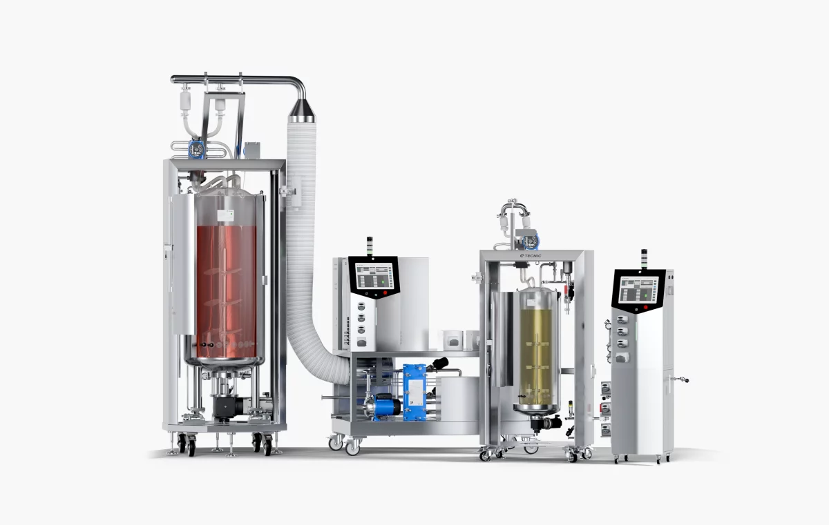
How the TECNIC vessel portfolio fits the workflow
TECNIC’s current vessel portfolio is useful because it does not present only one option. It gives laboratories a practical choice between reusable glass formats, simpler non-jacketed solutions and disposable vessel logic, depending on how the process needs to run.
Glass Reactor
TECNIC’s Glass Reactor range is aligned with controlled laboratory bioprocessing in 1, 2, 5 and 10 L, with reusable borosilicate glass formats and a jacketed configuration for tighter thermal control. The glass vessel catalogue also highlights upgrade and replacement flexibility for existing systems.
Non-Jacketed Glass Reactor
The Non-Jacketed Glass Reactor keeps the reusable lab vessel logic while simplifying the thermal approach. It is a strong fit where the process does not need the same level of integrated jacket control.
Single-Use Vessel
TECNIC’s Single-Use Vessel supports 0.5, 1, 2 and 5 L workflows with gamma-sterilised disposable product-contact paths, microbial and cellular agitation configurations, and ISO 7 manufacturing conditions.
Bioreactor Vessels overview
The overview page is useful as a bridge for users who are still comparing vessel formats before moving toward a more specific product decision.
This section stays technical on purpose. It helps the article rank more naturally for informational and comparative intent while still bringing the reader closer to a real TECNIC vessel path.
Frequently asked questions
What is the main difference between a glass reactor and a non-jacketed reactor?
The main difference is the thermal support approach. A jacketed glass reactor gives a more integrated heating and cooling path, while a non-jacketed reactor keeps the setup simpler and usually depends more on external temperature control methods.
When is a single-use vessel a better option?
A single-use vessel becomes attractive when reducing product-contact cleaning, simplifying changeover and lowering carryover risk are more important than keeping a reusable vessel path.
Do vessel geometry and ports really matter at laboratory scale?
Yes. They affect probe position, working volume, gas handling, additions, mixing and how reproducible the process remains from one run to the next.
Can the same vessel family support both microbial and cell culture work?
In many cases yes, but only if the agitation concept, porting and operating conditions are configured appropriately for the biological system.
What should I define first before choosing a vessel?
Start with the process objective, thermal needs, working volume, sterility strategy and how often the vessel setup is expected to change.
Looking for the right vessel format for your lab process?
Explore the TECNIC vessel range or speak with our team to review whether a glass, non-jacketed or single-use vessel fits your workflow more naturally.


